How to Build a Computer
This book goes from electrical signal → computer:
- Signals
- Switches
- Logic Gates
- Combinational Circuits
- Clocks and Oscillators
- Memory (Flip-Flops and Latches)
- CPU
- Instruction cycle
- Stored programs
1. Signals
How do you represent information physically?
A signal is a physical quantity used to represent information.
- Typically voltage levels in a wire
- Two stable regions are interpreted as:
- Low → 0
- High → 1
- Meaning is assigned externally (not intrinsic)
Other signals:
- Light pulses
- EM wave pulses
- Smoke signals
2. Switches
How do we control whether electrons can move from A to B?
- Mechanical → physically block path
- Vacuum tube → allow/block in empty space (1900s)
- Transistor → reshape material so path exists or not (1940s)
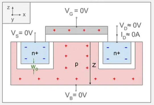
Transistor Basics
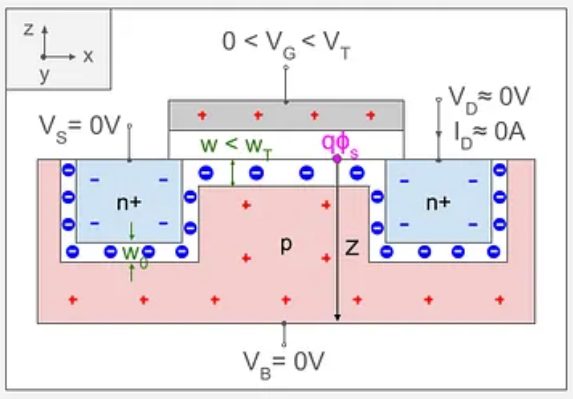
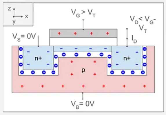
A transistor is a voltage-controlled switch.
- With no voltage on the gate → no conductive path → OFF
- Apply sufficient voltage to the gate → the electrical field pull electrons in the semiconductor to create a conductive channel → ON
- The gate does not carry the main current; it controls flow between source and drain
Gate Voltage = 0V
Gate Voltage < Terminal Voltage
Gate Voltage Greater than Terminal Voltage
3. Logic Gates
How do we build decision-making from switches?
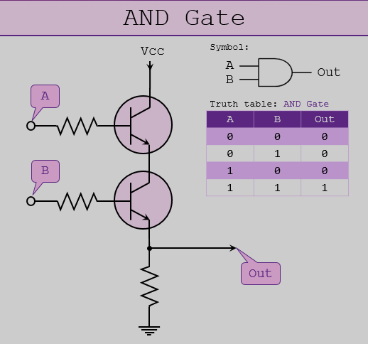
A logic gate is a circuit that gives different outputs based on the inputs.
Built from transistors arranged in a certain way so that voltage patterns implement rules of logic.
- Transistor = switch
- Gates = networks of switches
- Output depends only on current inputs
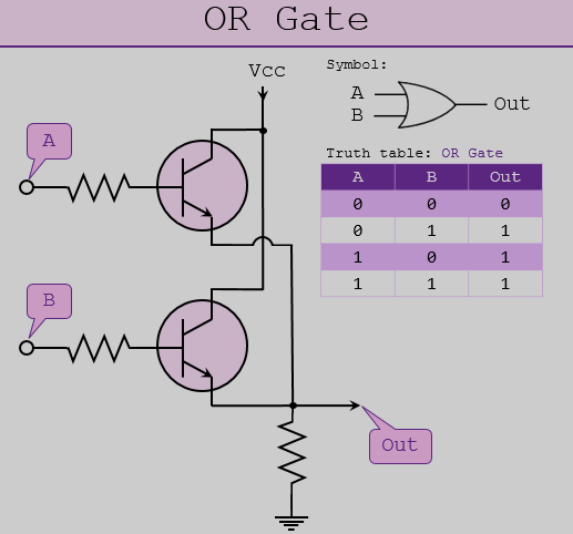
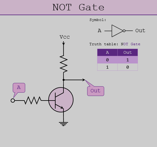
Logic gates are all connected to ground and a voltage source. The inputs enabling/disabling the flow from source to ground. Which is why a NOT gate can have a voltage output with no input (the input disables the flow).
3.1. AND
3.2. OR
3.3. NOT
These three are functionally complete → all computation can be built from them.
4. Combinational Circuits
How do we combine gates into useful operations?
Combinational circuits are logic systems with:
- No memory
- Output depends only on current inputs
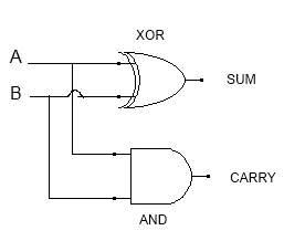
4.1. Half Adder
Adds two bits:
- Sum = XOR(A, B)
- Carry = AND(A, B)
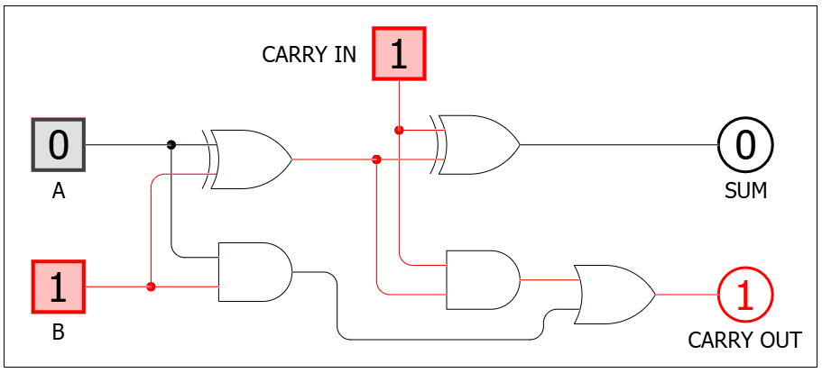
4.2. Full Adder
Combines two half adders:
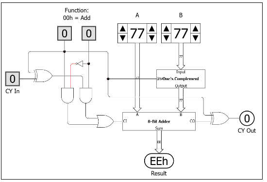
4.3. 8-bit Adder
Combines 8 full adders (uses 2s complement for subtraction):
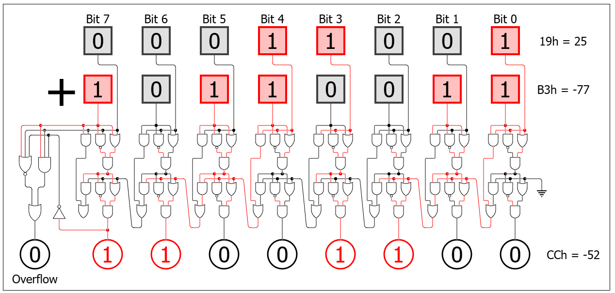
| A | B | Overflow | Outcome |
|---|---|---|---|
| + | + | 0 | No error |
| + | + | 1 | Error (sum too large) |
| + | - | 0 | No error |
| + | - | 1 | No error |
| - | + | 0 | No error |
| - | + | 1 | No error |
| - | - | 0 | No error |
| - | - | 1 | Error (difference too small) |
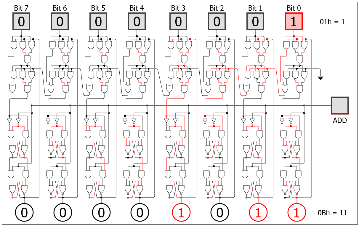
4.4. 8-bit Accumulating Adder
- Initially flip flops store 0.
- Flip flop output is routed to the full 8-bit adder input.
- The 8-bit input is the second input into the full 8-bit adder.
- The result of the full 8-bit adder is stored in the flip flops.
- The “add” is likely triggered by a clock cycle.
5. Clocks and Oscillators
How do we coordinate time in hardware?
A clock is a repeating electrical signal:
- 0 → 1 → 0 → 1 …
Without timing → circuits change unpredictably as switching components on/off is not synchronised
With clock → all components update in sync
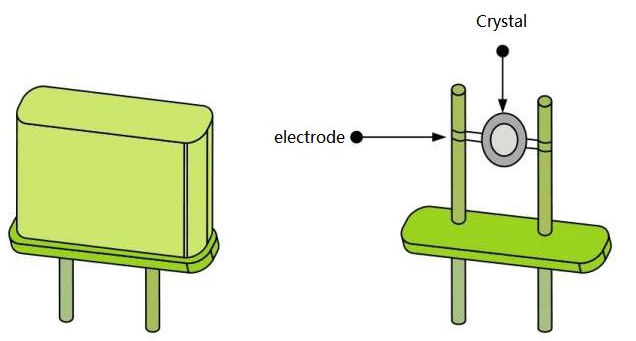
5.1. Crystal Oscillator
A current applied to the crystal (quartz) causes it to vibrate at a certain fixed frequency (dependant on size/shape etc).
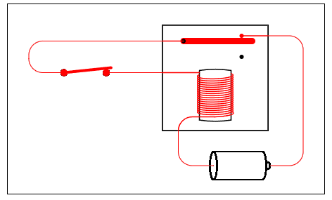
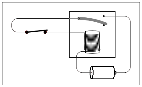
5.2. Oscillating Relay
A relay connected to itself causes it to switch itself on/off at a certain frequency (dependant on the length of metal switch)
6. Memory (Flip-Flops & Latches)
How do we store a bit?
6.1. Latch
Level-sensitive (state changes when clock is on)
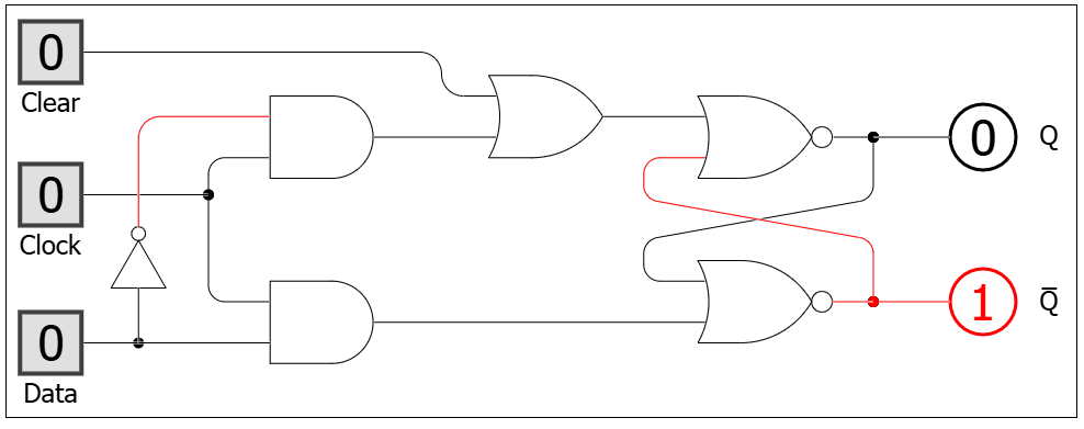
6.1.1. Level-triggered D-type Latch

6.1.2. Level-triggered D-type Latch with Clear
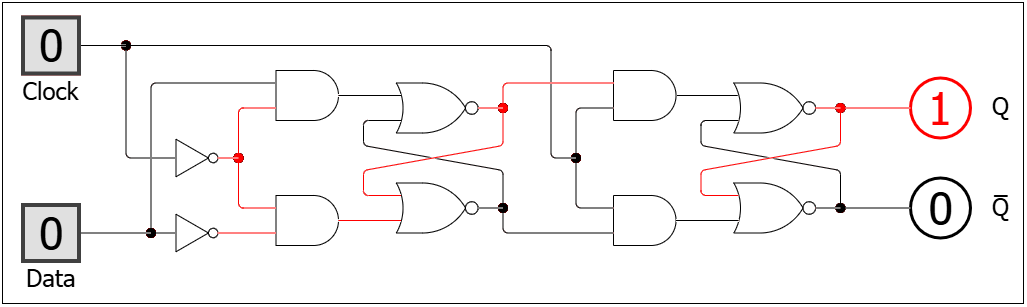
6.2. Flip-flop
Edge-triggered (state changes only on clock rise/fall)
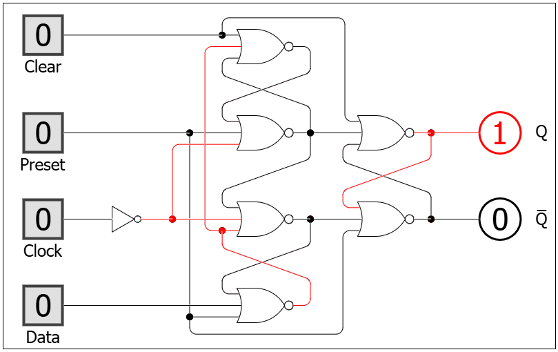
6.2.1. Edge-Triggered D-Type Flip-Flop with Clear and Preset
6.2.2. Edge-Triggered D-Type Flip-Flop with Clear and Preset
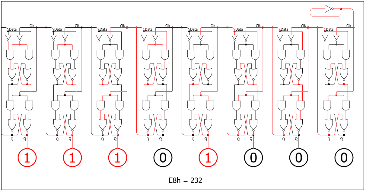
6.3. Binary Clock/Counter
If you connect a flip flop to an oscillator, the flip flop switches at half the frequency. Connecting multiple flip flops creates a binary clock. As each one oscillates at half the frequency of the previous one.
7. CPU (From Parts to System)
How do we combine memory and logic into a machine that can execute instructions?
A CPU is built from:
- Registers (small fast memory)
- ALU (calculation unit)
- Control Unit (decision logic)
- Buses (communication)
7.1 Registers
Where does the CPU store values it is actively working on?
A register is:
- A group of flip-flops (8 bit register shown below)
- Stores a fixed number of bits (e.g. 8-bit, 16-bit)
Types of Registers
7.1.1. General Purpose Registers
- Used for temporary values
- There are normally 5-10 of these
- Example:
- Store numbers for calculations
- Hold intermediate results
7.1.2. Special Purpose Registers
- Program Counter (PC)
- Holds address of next instruction
- Instruction Register (IR)
- Holds current instruction being executed
- Accumulator (ACC)
- Stores results of ALU operations
- Memory Address Register (MAR)
- Holds address for memory access
- Memory Data Register (MDR)
- Holds data being read/written
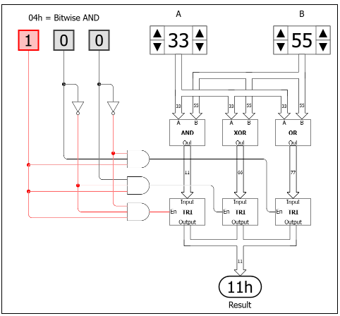
7.2 ALU (Arithmetic Logic Unit)
How does the computer actually compute?
The ALU is a combinational circuit (no storage) that performs arithmetic and logic operations:
- Addition
- Subtraction (2’s complement)
- Bitwise logic (AND, OR, NOT, XOR, shifting etc.)
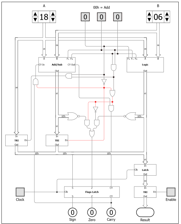
How it Works
- A - input into ALU
- B - attached to accumulator register
- F2, F1, F0 - control bits that activate the circuitry to perform a specific function
- Flags - indicators raised on the current operation
Add/Sub Module
Logic Module
7.3 Buses
How do all components share data?
A bus is a shared set of wires between components. It can only be in use by one component at a time otherwise it will short circuit or produce garbage output.
Types of Buses
- Data Bus → carries actual values
- Address Bus → selects location
- Control Bus → carries signals (read/write, enable, clock)
7.4 Tri-State Buffers
How do we prevent components from “talking over each other” on the buses?
A tri-state buffer has 3 states:
- 0 → drives line low
- 1 → drives line high
- High impedance (Z) → disconnected
This allows:
- Only one component to drive the bus at a time, others remain electrically invisible
- When components are “enabled”, they are connected to the buses.
- Once the CU decodes an instruction, it enables/disables components to connect them to the buses.
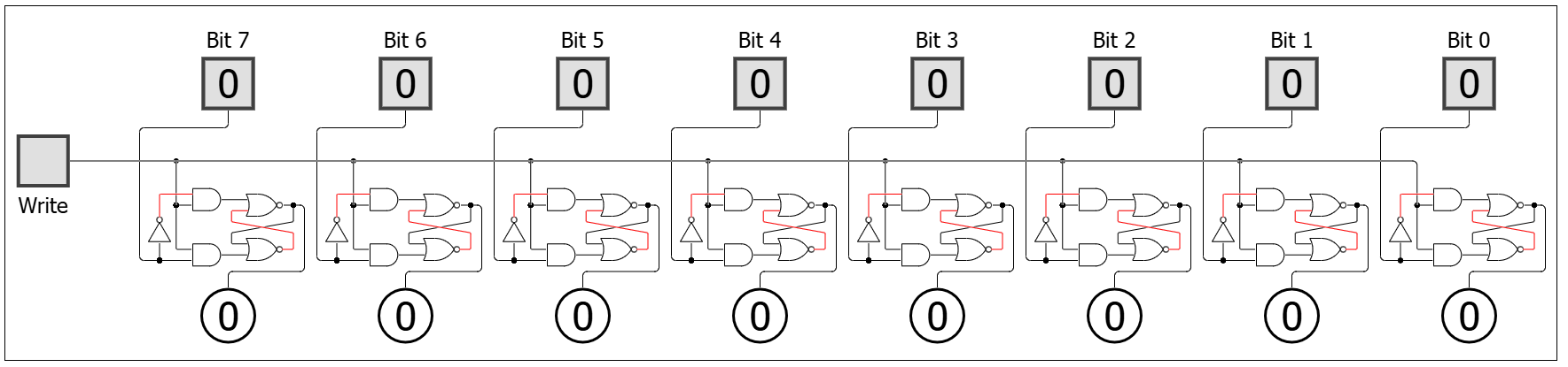
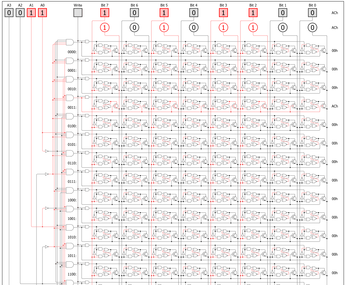
7.5 RAM (Main Memory)
Where are programs and data stored long-term (during execution)?
RAM is:
- A large array of flip flops (16 x 8 bit flip flops in image below)
- Each byte is indexed by an address (4 bit address below)
- The address enables a row/column in the array
- Once enabled, the output of RAM is set to the contents at the address
- If written to, it changes the content at that address
- An address refers to one 8-bit location (1 byte)
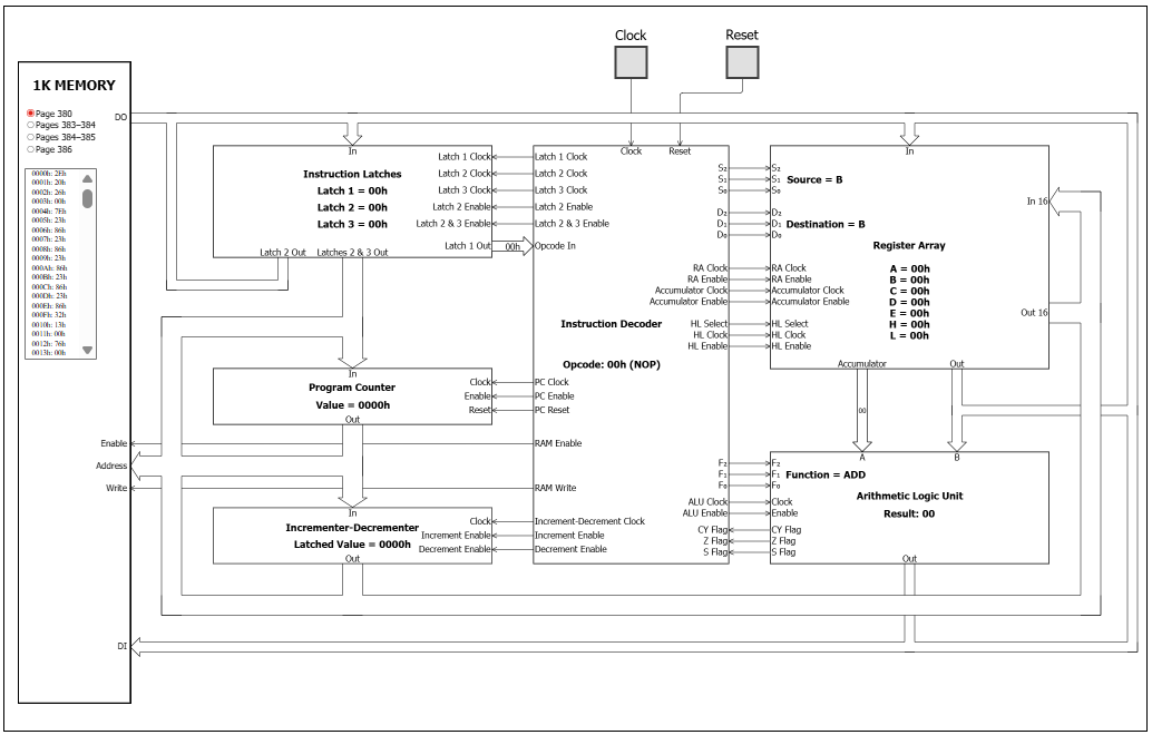
7.6 Control Unit (CU)
What tells everything when to act?
The Control Unit contains the following subcomponents:
- Instruction latches
- Instruction decoder
- Program counter
What it Does
- Reads instruction from RAM into instruction registers
- Decodes opcode (by responding to bit patterns in the opcode itself)
- Enables/disables parts of the CPU through control signals:
- Registers (load/clear)
- ALU operation selection
- Memory read/write
- Bus access (via tri-state buffers)
No intelligence. Just:
- If opcode = 0001 ADD control signal is active
- If opcode = 0010 LOAD control signal is active
8. Instruction Cycle
How does the whole system actually run?
Repeating process:
1. Fetch
- The PC (program counter) is enabled onto the address bus
- RAM (memory) is enabled on the data bus, the opcode at that address is returned
- The IR (instruction register) is enabled on the data bus and the opcode is stored in the IR
2. Decode
- CU interprets opcode (by responding to bit patterns in the opcode itself)
3. Execute
- CU activates:
- Registers
- ALU
- Memory
- Buses
4. Update
- Result stored in RAM
- PC incremented
9. Stored Programs
What makes this a general-purpose computer?
Instructions are stored in RAM just like data.
So:
- Data = numbers
- Instructions = also numbers
This allows:
- Programs to be loaded, changed, reused
- Same hardware → many different behaviors
9.1 Machine Code
What does the CPU actually understand?
The CPU only understands binary instructions:
- Example:
0001 0010→ might mean “ADD register A and B”0010 0100→ might mean “LOAD from memory”
These are called machine code instructions:
- Each instruction = opcode + operands
- Interpreted directly by the Control Unit
This is the real language of the machine.
9.2 Assembly Language
How do humans work with machine instructions?
Assembly is a human-readable version of machine code.
Instead of:
0001 0010
We write:
ADD A, B
Key points:
- One-to-one mapping with machine code
- Still very close to hardware
- Uses symbolic names for:
- Instructions
- Registers
- Memory addresses
An assembler converts:
Assembly → Machine code
9.3 High-Level Languages
How do we write complex programs efficiently?
High-level languages (e.g. Python, C, Java) are:
- More abstract
- Closer to human thinking
- Independent of specific hardware
Example:
x = a + b
This gets translated into many assembly instructions.
9.4 Compilers
How do high-level programs become machine code?
A compiler translates:
High-level language → Machine code
Steps (simplified):
- Parse code (understand structure)
- Optimise (improve efficiency)
- Generate assembly/machine code
Some languages use:
- Interpreter → runs code line-by-line
- Compiler → produces executable file